Trying to improve mipmap blending
LINEAR_MIPMAP_LINEAR, blending from one mipmap level to the next,
is an interesting bodge. It approximates a dynamic cut-off frequency
with linear interpolation between adjacent log2 cut-off
frequencies.
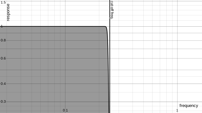
To set a baseline, what we want from the ideal texture unit is to cut
all the signal content above the cut-off frequency implied by the
distance between pixels of the output:

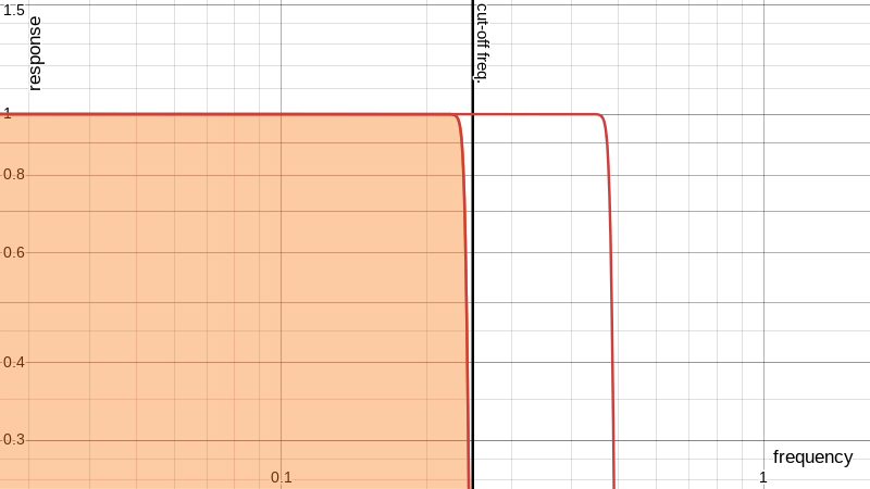
What we actually get from mipmapping is a linear blend that produces
this rising shelf effect as the cut-off transitions between two adjacent
mipmap levels:

I don’t imagine it’s usual to go looking at the frequency response of one axis of the transfer function of image processing operations. But that’s what I’m doing today.
For those not used to seeing it, that crack between the ideal signal and the cut-off frequency is a practical limit of resampling; and for the sake of clarity I’ve used much sharper band-limiting filters than are realistic (or prudent), and I’ve ignored the high-frequency rolloff and clipped off what would alias as a consequence of linear interpolation. And I put the vertical frequency cut-off line where I wanted it, without regard to the programmability of the LOD bias, or whatever its default position would be.
So what we see in these plots is that all the mip levels agree on the low-frequency content of the image, but they cut off at regular intervals (regular in the log domain), and when blended from one to the next the low-frequency content is not affected but high-frequencies come out as something not ideal.
There are two bad things of note. One is that the signal extends beyond the cut-off frequency. That’s where aliasing comes from. The other is that during much of the transition the high frequencies don’t go all the way up like they should.
But let’s not overlook that this is mostly illustrative.
Musing about how to mitigate this I started experimenting with pre-filtering the mipmaps and then fixing them after the blend and resapmling operation. In the frame buffer.
This makes it a very limited-use remedy and it would be challenging to fit into a generic 3D pipeline. But if it does work then there are situations where it could be used.
My idea is to apply a sharpening post-filter to the result of the texture lookups – to the output samples after they’ve been mip-mapped and sampled. Since that would be applied after resampling the correction filter cannot depend on the specifics of the mip level, which varies on a per-pixel basis (unless maybe we stored the effective LOD in the alpha channel?). All pixels should benefit equally from an identical filter.
For that to work we need the above graph to show a frequency rolloff which is comparatively smooth and consistent regardless of where the cut-off frequency is in relation to the mip levels. We can’t just have these elevator steps.
My first naive thought was to replace the steps with ramps which, when blended together, would give the impression of a ramp moving smoothly left and right. A correction filter to fix that that would be simple.
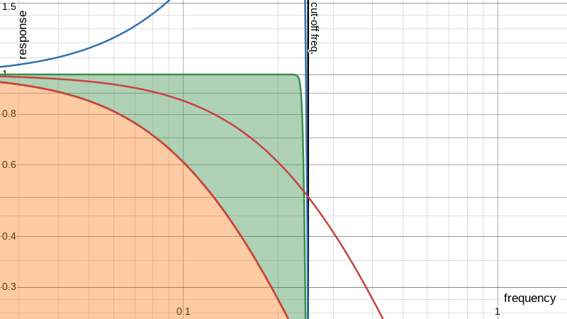
If that was going to work, and if I used a 1-pole filter to make the
ramp, it might look a bit like this:
 (blue line is the correction filter and green is the recovered passband)
But it’s not going to work because that ignores the fact that the source images are band-limited. So there’s going to be some kind of unavoidable inflection point in the curve representing that hard stop. Sort of. It’ll actually be filled in with aliasing noise from linear interpolation, which makes analysis kind of hairy.
There’s a bunch of signal processing theory goes here, but for expediency I just pressed on with truncated passbands to see what’s feasible. And it looks like this technique could actually help:
This could be tuned a lot better with proper models of linear interpolation and a filter directly tuned to minimise the error across the whole pass band and give a clean roll-off and blah blah blah filter-design blah.
But all of this is a 1D theoretical model with idealised band-limiting in the mipmap interpolation. It would make more sense at this point to defer to real-world implementation and experimentation.
I don’t have time for all that, so here’s another one where I just used slightly more realistic filters, and then hacked things around a bit trying to make the pass band pump a bit less at the expense of a flat passband (I’m sure it’s fine!):
Still, let’s not forget that all this does nothing to help with mip-mapping’s other failure case where one axis is compressed differently from the other.
And, as mentioned, the post-filter makes this for niche application only. In a typical 3D scene one has other things going on, like the edges of the textures and horizons with unrelated texture data.
Maybe something like oversizing the geometry would make it possible to use alpha blending around the edges to mimic the blur which the sharpening will counteract. But that would probably end up way more expensive than supersampling.
But if it’s part of a simple image warping pipeline this might be practical.